This is a low earth dam without corswall, and, aside from minor items of depreciation and the growth of trees on the easterly portion of the embankment, the structure is in good condition.
The top elevation of the embankment is 1100.00 (USGS) and in 1936-37 a new spillway was constructed, 24 feet long with stop-logs and by-pass, permitting the lake level to be regulated between 1096.00 and 1090.00 (USGS). Floods have been controlled in the past chiefly by impounding the water in Canadice Lake, with manual operation of the stop-logs during floods. The 40-year record of lake levels and outflow kept by the City shows that it is necessary to provide for a flood runoff equivalent to 5 feet depth on the lake, with a maximum inflow rate of 2400 cfs, with the reservoir initially full. Heavy floods occur usually in late fall or in the spring months, more commonly the latter, after the reservoir has been filled. The flood requirements can be met by construction of a new spillway with 100-foot crest length at the west end of the present dam, where better foundation conditions are available than in the valley bottom. The combined spillways will take care of a flood such as described, with a rise in the lake of less than 2 feet above spillway crest and without removing the manually controlled stop-logs in the present spillway.
To provide increased storage the new spillway crest would be at elevation 1099.00 (USGS) and the present spillway would be raised from elevation 1096.00 to 1099.00 (USGS), the embankment would be raised to top elevation 1105.00 (USGS), with side slopes 1 on 2.5 and 1 on 3 on the land and water sides, respectively, and with top width 12 feet, the top being used as a roadway from the east to the spillway.
Surveys, borings and plans for the main features of the work have been completed. Reconstruction of Canadice dam requires practically no metal or defense material, as it will be constructed wholly of earth, cement and stone.
The City now has the right to regulate water levels in Canadice Lake between any desirable limits, and owns the land on which the reconstruction would take place. There is certain preliminary work which can be carried out this fall and winter, including clearing of lands to be flooded at the head of the lake, certain highway improvements and acquisition of cottages adjoining the head of the lake. The construction of the dam could then be carried out in 1944.
Raising the Canadice dam to flow line elevation 1099.00 (USGS) will provide 740 million gallons of additional storage and will provide a total of 2,000 million gallons storage which can be drawn by gravity through the present outlets in the dam.
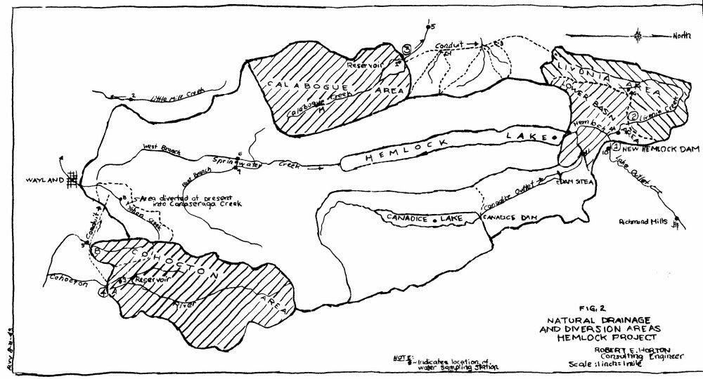
To completely regulate Canadice Lake and avoid waste of water requires a much large volume of storage and greater depth of draft. To obtain this additional storage will require provision for drawing Canadice Lake down to elevation 1080.5 (USGS) or 9.5 feet below the present minimum draft level. This additional storage can be obtained either by low-lift pumping from the lake into the present Canadice Lake channel below the dam or by the construction of a new low-level outlet, which will permit this additional storage to be drawn by gravity. The flat bottom of Canadice valley is at elevation 1091.00 (USGS) just below the dam and slopes gradually to 1080.3 near the Canadice town line, 8,000 feet to the north. Provision for drawing the lake to the required level by gravity could be made either by construction of an open channel or a concrete conduit throughout this length or by construction of an open channel for emergency use during the war period, to be followed later by laying of a conduit in the channel as a post-war project. Neither of these two methods would require defense material and most of the land through which the drain conduit would be laid is now owned by the City. In either case a diversion conduit would be constructed from deep water in Canadice Lake, around the east or right-hand end of the dam (looking downstream), leading into the new drain channel or conduit. Surveys have been made and underground explorations are in progress along the route of this proposed conduit and it is intended to complete plans so that provision for complete regulation of Canadice Lake can be made at the same time that the reconstruction of the dam is carried out. This increased use of Canadice Lake storage will provide an increase of available supply of roundly 2.3 mgd.
Pending construction of the new Hemlock dam, water derived from Canadice Lake and Outlet must be diverted into Hemlock Lake through the present Canadice intake and diversion conduit. Recently the lip of the Canadice Outlet conduit in Hemlock Lake was raised and gates provided to prevent back-flow from Hemlock Lake into the conduit and reduce loss by leakage. These gates will also permit the conduit and making temporary repairs. In addition they will prevent the loss of a large volume of storage from Hemlock Lake which would occur in the event of a break or blow-out of the roof of the conduit.
The new Hemlock Reservoir will be formed and controlled by the dam located one-fourth mile upstream from the village of Hemlock. The dam will have a fixed spillway at elevation 403.00, with a crest length of at least 300 feet. The overall length of the dam will be 2,400 feet. The dam will consist of heavy earth embankment with a reinforced concrete corewall extending from the top down either to rock or to a depth below the natural ground surface at least equal to the depth of water at the same location, thus insuring water-tightness.
The natural stream bed at the location of the dam is at elevation 378.00 and 376.00 at the sight of old Hoppaugh dam. The maximum height of dam from stream bed to top of embankment would be 30 feet. This is a relatively small dam and would be constructed of earth, cement and stone, and it would require no considerable amount of defense material of any kind, the principal items being steel for the corewall etc., and the valves and pipe fittings in the Gatehouse.
The reservoir formed by this dam will comprise two basins, the lower basin extending from the new dam to the present Hemlock Lake dam, the upper basin covering Hemlock Lake as at present but with normal flow line from elevation 397.5 to elevation 403.00.
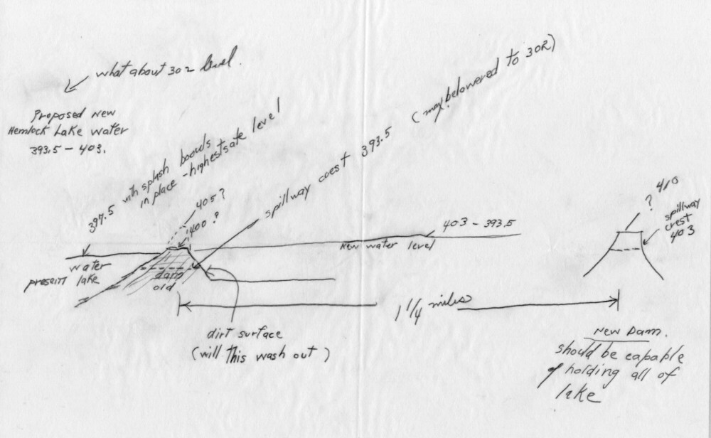
The spillway weir crest at the present Hemlock Lake dam is at elevation 393.5. The drop timbers in the spillway would be removed and the present Hemlock Lake dam retained, but with water at elevation between 393.5 and 403.00, water would stand at the same elevation above and below the dam, and the present spillway would no longer be used as a spillway but merely as an outlet channel.
The elevation of Hemlock Lake Outlet just downstream from the present spillway is 386.00 and the elevation of the floor of the apron of the spillway is 386.8. With the water drawn below elevation 393.5 the upper and lower basins of the reservoir would be separated and they could of course be kept entirely separate at any time by replacing the drop timbers in the spillway. With present Gatehouse No. 2 retained and in operation, the lake could be drawn down to 381.0.
With water in the present lake at elevation 393.5 or lower, there would be a slight difference of elevation of water in the two basins of the reservoir. The lower basin reservoir would be nearly rectangular in form and would have an area at elevation 403.0 of 450 acres or 0.7 square mile, and a useable volume between elevation 403.0 and 381.0 of 1530 mg. The maximum depth of the reservoir at the dam site would be 27 feet, (leaving 3 feet to top of dam) its average depth of 10.4 feet, its length 6,000 feet or 1.14 miles and its average width 3,200 feet. It is therefore, considered by itself, neither a small nor a shallow reservoir.
Under normal operating conditions, drawing the entire supply from the Gatehouse at the new dam, a large portion of the water used would come from Hemlock Lake and would flow down through the lower basin of the reservoir, thus maintaining continuos circulation. With, for example, a draft of 40 mgd, and without bringing in other areas, the part of supply drawn, respectively, from the upper and lower basins of the reservoir would be approximately or 27 mgd from Hemlock Lake through the lower reservoir and or 13 mgd directly from the lower reservoir. The proportions drawn from the upper and lower basins of the reservoir will be little changed when the Calabogue and Cohocton areas are brought in.
The bottom of the lower basin reservoir, between Hemlock village and Hemlock Lake, is mostly clean cultivated soil, with areas of timber and low ground along the stream. The trees and stumps would be removed and the vegetal matter, roots, humus etc. remaining in the ground on these areas would be covered with a layer of clean mineral soil taken from the new channel or elsewhere within the reservoir basin.
Some organic matter of vegetal origin invariably remains in the bottom of such a reservoir when first put in use. This material is changed chemically and gradually absorbed by the water when the reservoir is first put into use and may produce color, odor and taste for a time if the water is allowed to remain too long in the bottom of the reservoir. This is a condition common to new reservoirs created by flooding lands and would also occur if the City went to some other stream instead of building a new dam at Hemlock. The occurrence of water of poor quality in the bottom of a reservoir is related to the depth of the reservoir and this condition is much more aggravated in deep reservoirs than in reservoirs of moderate depths, such as that proposed at Hemlock, where circulation of air, oxygen and sunlight can penetrate nearly to the bottom of the reservoir. There is nearly an ideal depth of reservoir, ranging from 25 to 35 feet, depending on conditions. The occurrence of undesirable water in the bottom of a new reservoir is not a dangerous condition. In this case there is a simple remedy. During the first few years of operation of the project there would be an excess of available supply over water requirements of Rochester. Instead of wasting this excess over the spillway it should be drawn from the bottom of the reservoir at periodic intervals. In the meantime water used from the Lower Basin should be drawn rom near the surface and suitable intake openings at two or more levels in the gatehouse would be provided for this purpose. This practice has been used elsewhere with satisfactory results during the first few years of operation of a new reservoir while the bottom is undergoing a curing process.
The new dam would be upstream from the village of Hemlock. A portion of the lands flooded by the Lower Basin, comprising those within the flow line of the old Hoppaugh mill dam, are now owned by the City. No first-class highways would be interfered with. About one half-mile of second-class highway now running to the foot of Hemlock Lake would require abandonment or relocation. Livonia Creek would enter the Lower Basin from the west and a low portion of the highway along the west side of the Lower Basin would be raised and used as a dike to form a settling basin for the waters of Livonia Creek. A drain from this basin to a point on Hemlock Lake outlet below the new dam would permit low water flow from Livonia Creek to be discharged into Hemlock Lake Outlet. A spur of the Lehigh R.R. leading to the canning factory at Hemlock would require relocation if continued in use, the relocated length being about three-fourths mile.
The original Hemlock Lake dam was completed in 1875 and was constructed over and on the site of a preexisting timber mill dam and embankment, with the crest of the dike or embankment at elevation 390.0 (898.3 USGS).
The following quotations are taken from the Annual Reports, Division of Engineering, Rochester 1928-1936, (p.69).
"Plans for increased storage in Hemlock Lake were first put in effect in 1909 by the construction of a concrete spillway having four openings each six feet wide. The crest of spillway was built to elevation 393.5' (H. D.). The construction of this original spillway was followed in 1913 by the raising of the dyke to elevation 395' (H. D.).
In November 1927, the dyke was again raised an additional five feet to elevation 400' (H. D.). A concrete spillway, similar in construction to the old one and having the same number of width of openings was constructed in the same location and on top of the old spillway. The new crest of the spillway was built to elevation 394.5' (H. D.) With flashboards provided for raising the water level in Hemlock Lake to a safe maximum storage elevation of 397' (H. D.)."
In 1936 a new spillway was constructed at the location of the old natural outlet of the lake, about 220 feet to the west of the existing channel.
"The new structure consists of a concrete spillway of the ogee type having eight openings, each with a clear width of eight feet, a total width of 64 feet. The spillway crest is at elevation 393.5' (H. D.) (901.8' USGS)."
"....... The whole structure, excepting the concrete floor of the channel, is built on timber piles ranging length from 40 to 60 feet. A cutoff wall consisting of sheet metal piling was driven under the main spillway wall and a steel toe wall driven under the downstream end of the concrete channel."
The construction of the new spillway the remains of the original mill dam were encountered in driving piling. There had been a slight settlement of the new spillway and it has not been considered safe to maintain the water at higher elevations than 397.0 to 397.5. The trouble is with the foundation rather than the superstructure and cannot certainly be easily remedied by repairs to the latter. The spillway is not automatic in operation but requires manual operation of the steel flashboards. The length and capacity of the spillway are less than is desirable.
The embankment constructed of earth and, so far as known, without any corewall or cutoff wall of any kind excepting at the spillway.
With the new dam at Hemlock village the water would stand at nearly the same elevation upstream as downstream from the present dam at all high stages of the stream and no question of safety would arise. The drop timbers will be removed from the spillway and the present Hemlock Lake spillway will operate as a discharge channel rather than a spillway. The crest of the earth embankment will be raised and paved on the water slopes to prevent over-wash by waves.
The spillway at the present Hemlock Lake dam has 8 bays, each 8 feet wide, separated by 2-foot piers, with a fixed crest at elevation 393.5. Stop-logs are kept in place in the spillway bays, usually to elevation 397.5 in the two end bays, and are manually operated as required during floods, in the six intermediate bays. With present maximum flow line 397.5 this spillway has a capacity of about 1800 cfs if all stop-logs were removed.
In comparison it is proposed to provide a fixed spillway at Hemlock Lake in connection with the new project which will automatically take care of the maximum flood from the drainage area with a maximum outflow depth of about 3.5 feet above spillway crest level.
The spillway at the present Hemlock Lake dam will be used solely as a connecting channel between the upper and lower basins of the reservoir. Removing the stop-logs and lowering the fixed crest to elevation to 392.0 will provide a channel section of 704 feet square feet below elevation403.0. This will be capable of discharging a flow of 7,000 cfs at a permissible velocity of 10 feet per second with a head loss or drop of level between the two reservoir basins of about 2 feet.
Consideration was given to the construction of a new dam to flow line elevation 403.0 immediately downstream from the present dam. Because of the character of the foundation this would require a deep cut-off wall, preferably of steel sheet piling, which is not at present available. A new dam can be constructed at the site chosen near Hemlock, with better foundation conditions and at less cost and without the use of steel sheet piling. A dam at this location will also provide much needed additional drainage area and storage and greater flexibility of operation, by providing two storage basins, from either or which the supply can be drawn.
A new gatehouse, designated Gatehouse No. 3, on rock foundation, would be constructed at the new Hemlock Lake dam, together with a new supply conduit, about 5,500 feet in length, leading to Overflow No. 1. The length of the present 6-foot brick tunnel from Gatehouse No. 2 to Overflow No. 1 is 11,892 feet. Because of the shorter length,, with water in the reservoir at the same elevation, the new main supply conduit, if of the same diameter, would deliver both a greater quantity of water at Overflow No. 1 and deliver it at a higher elevation.
Under present conditions it is necessary to pump water under a low head from Overflow No. 1 to feed to feed the restored portion of Conduit No. 1 to Rush Reservoir. This pumping is necessitated by the fact that the present brick tunnel does not deliver water at Overflow No. 1 at a sufficiently high level. This condition would be remedied upon completion of the new main supply conduit to Overflow No. 1. This conduit would enter a concrete standpipe located adjacent to the present building at Overflow No. 1, with outlets arranged so that the present
Conduits Nos. 2 and 3 could be fed either as at present from the 6-foot brick tunnel or from the new supply tunnel, while Conduit No. 1 and any future additional conduit constructed to convey water to the City would be fed ordinarily from the new supply tunnel but could be fed from the present 6-foot brick tunnel. This would provide increased flexibility of supply and would make it possible to continue the supply with the present 6-foot tunnel shut off for inspection or repairs.
The new main supply conduit would have a capacity of about 65 mgd, adequate to take care of fluctuations in demand as well as to maintain a continuous supply of 50 mgd. The present brick tunnel has a capacity to deliver 40 mgd at Overflow No. 1.
The construction of the gatehouse and new main supply conduit to Overflow No.1 could be carried out either in conjunction with or immediately following the construction of the new dam, while the reservoir is being filled. Upon completion of the new dam and main supply conduit, together with the complete regulation of Canadice Lake, the Hemlock system would provide a minimum dependable supply of 40 mgd, made up as follows:
						From regulated Canadice Lake  ............	 7.5 mgd
						From the new Hemlock Reservoir ...........	32.5 mgd

							Total ............................	40.0 mgd
These figures include the additional supply obtained from the restoration of the head-water tributary of Springwater Creek to the Hemlock Lake drainage basin, but not the Calabogue and Cohocton areas.